Features
Licensing
Downloads
Pricing / Order Form
Video Tutorials
|
|
 |
Free to Try - the full install can be downloaded - click the Downloads link on the left
|
User Interface |
|
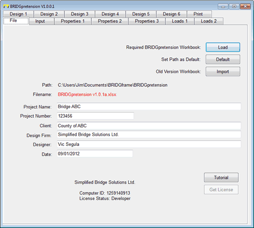
File
- user interface is a Microsoft Visual Basic tabbed dialog with 14 tabs including 3 for Properties, 2 for Loads, and 6 for Design
- the dialog is filled from the Workbook identified in the Load button procedure
- path of file may be defaulted to simplify loading of files
- analysis and output is implemented on Excel Workbooks, one per project
- older version workbooks can be easily imported into the current version
|
 |
| |
|
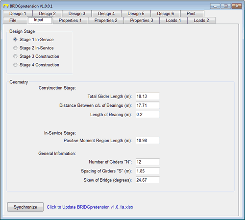
Input (Stage 1)
- design process is divided into stages which are normally selected in order
- used to specify basic geometry of the girder and general bridge arrangement
- the Visual Basic tabbed dialog and the associated Excel workbook are adjusted to display only the details required for the Design Stage selected
- in Design Stage 1 the Geometry of the girder is specified
|
 |
| |
|
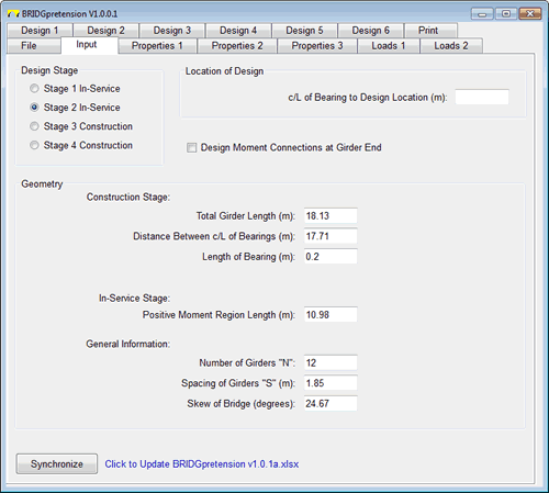
Input (Stage 2)
- in Design Stage 2 the Location of the Design is specified
|
 |
| |
|
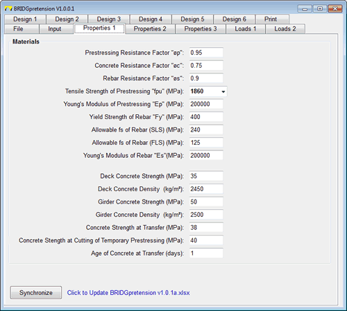
Properties 1
- used to input the material properties and design parameters
- tab is not editable for Design Stages 2 and 4
- the Properties 2 tab is used to input the Mid Span section properties
- the Properties 3 tab is used to input the Girder Ends section properties and the length of application
|
 |
| |
|
Loads 1
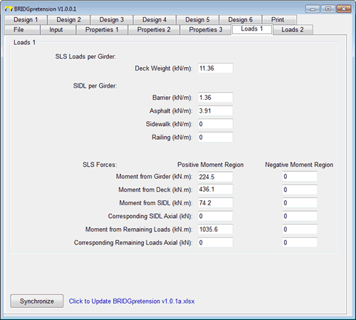
- linear weight per meter of the dead and superimposed dead loads is defined
- SLS forces from pre-established force envelopes using BRIDGframe or equal are entered
- the Loads 2 tab is used to enter ULS and FLS force envelopes
|
 |
| |
|
Design 1
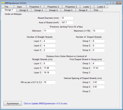
- values entered in Design Stages 1 and 3
- pretensioned strand section properties is input
- define cross sectional layout of strands within midspan region
- automated calculation of required jacking force
|
 |
| |
|
Design 2
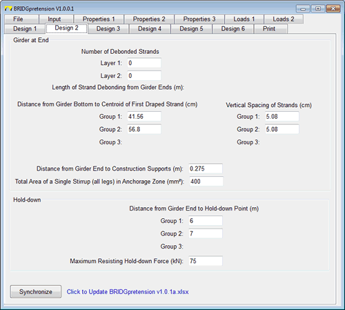
- values entered in Design Stages 1 and 3
- define cross sectional layout of strands at girder end
- designate hold down locations of draped strand groups
|
 |
| |
|
Design 3
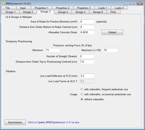
- values entered in Design Stages 1 and 3
- for ULS design at midspan, additional rebar may be added
- if applicable, temporary pretensioned strands may be added to the girder top to counter primary pretensioning at transfer
- automated required jacking force determined for temporary strands
- vibration is checked at this stag
- the Design 4 tab (for Design Stages 2 and 4) is for user desfined design locations
- the Design 5 tab (for Design Stages 2 and 4) is for shear design
- the Design 6 tab (for Design Stages 2 and 4) is for the design of the shear interface between girders and deck
|
 |
| |
|
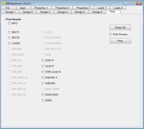
Print
- simplified printing of Excel worksheets with project information included in preformatted header and footer
|
 |
| |
|


